日本語
日本語 400Hzトランスの基本原理
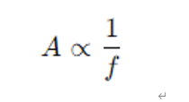
トランスのサイズは、その動作周波数と密接に関係しています。トランス設計において、コアの断面積は通常、動作周波数に比例します。
したがって、動作周波数が50Hzまたは60Hzから400Hzに増加すると、必要なコア体積を大幅に削減できます。
一般的な航空機用電源システムでは、電力変換プロセスは通常、以下のステップを含みます:
- 1. 機内の直流電源(例:28Vまたは270V DC)または周波数変換された交流電源を整流します。
- 2. インバータを介してPWM技術を使用し、安定した400Hzの交流電源を生成します。
- 3. **400Hzトランス**は電圧調整(例:115V/200Vへの昇圧)を実行し、電気的絶縁を提供します。
この構造により、400Hzトランスは電力変換プロセス中に、**電圧変換、システム絶縁、および電力品質の安定化**という重要な機能を同時に担います。
磁性材料と構造最適化
より高い動作周波数に対応するために、400Hzトランスは通常、以下の材料と技術を採用します:
- 1. 薄いケイ素鋼板の積層構造(厚さ約0.1~0.2 mm)
- 2. アモルファス合金コア材料
- 3. 低損失フェライト材料
これらの材料は高い透磁率と低い渦電流損失を持ち、トランスの効率を大幅に向上させ、発熱を低減します。
![[TREND]-400Hz电源技术的发展趋势](https://www.sikes.jp/wp-content/uploads/2026/03/tmp_07-500x303.png)