日本語
日本語 


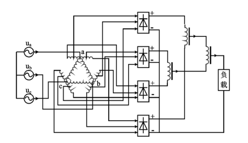
- Simple structure
- Low cost
- High reliability
-
Power Quality FiltersFor Motor ProtectionEMC/RFIAC/DC ReactorsPower TransformersLoad BankRegenerator and Brake ChoppersPower ResistorsHigh-Voltage Soft Starter
-
- すべての製品
- AC Line Reactor
- AC Output Reactor
- APF Filter Reactor
- DC Built-in Reactor for Inverter
- DC Filters for Rail Transit
- DC Reactor
- Detuned Reactor
- Epoxy-resin filled Dry-type iron core series Reactor
- Filtering Reactor for Regenerative drive & Photovoltaic
- Load Reactor for load test simulator
- Si-Fe Magnetic Core DC Reactor
-
- すべての製品
- Auto Transformer
- Control Transformers
- High-impedance Isolation transformer
- Isolation transformer
- Photovoltaic isolation transformer
- Rectifier transformer
- SC(B)Epoxy-resin filled Dry-type electric transformer
- Three phase to single phase transformer
- Transformer for Aerospace & Military
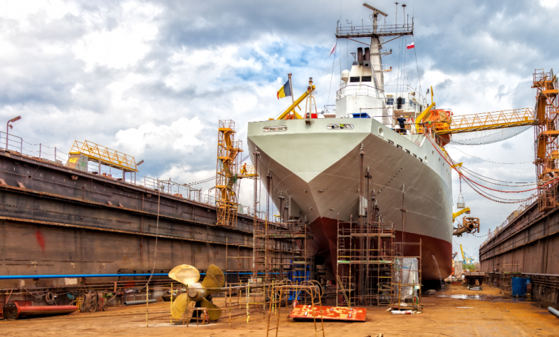
- Waterproof transformers for ship
- ZYSFG Phase-shifting rectifier transformer
-
- すべての製品
- Adjustable Resistor
- Aluminum Housed Resistor
- Aluminum Resistor Multi-Unit
- Braking Resistor Box, Resistor cabinet
- Golden Aluminum Housed resistor for led
- RI82/RI80 Glass Enamel High-Voltage Resistor
- Neutral Grounding Resistor
- Stainless steel resistors
- Vitreous enamel resistor
- Wirewound Resistor
お探しの製品が見つかりませんか? -
Harmonic Solution for VFD system & EC FanHarmonic Solution for Medium frequency furnaceMotor Protection solutionEMC/RFI ProductsSolution for Load testingBraking Solution for VFD SystemPower Supply for Aerospace & MilitarySolutions for Grid ConnectionTransformer for Electroplating Field